Introduction
The main aim of this blog is to reflect on and record the various workshops I have completed. I will express my thoughts on what I experienced, the difficulties and triumphs. The workshops have been chosen based on methods and techniques that I am unfamiliar with. Therefore I will expand my skill set through this process. This page will focus on the different digital software that I have used and all of the various methods and techniques that I have learned which I can apply to future projects.
Rhinoceros 6
The main software that was used in this workshop was ‘Rhinoceros 6’. Rhino is a 3D modeler which is used to create, analyze, edit, document, render, and translate all types of shapes, curves, surfaces and solids.

Initially when using Rhino the first step was getting used to the four multi-screen dynamic. The reason for this style of modeling is to enable the user to see four different perspectives, top, front, right and perspective. I learned this can be useful in trying to efficiently create shapes and perceiving them in every angle.
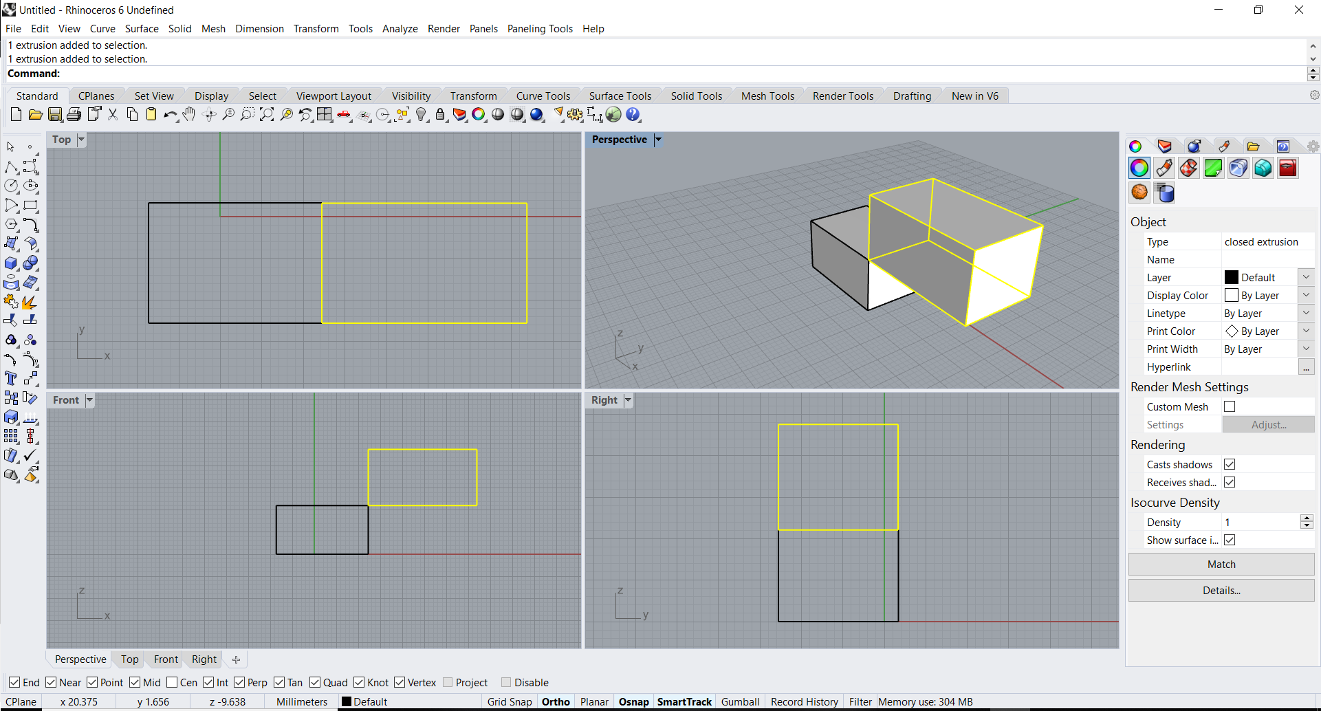
The first tutorial session consisted of familiarising myself with the basic commands and methods in order to create simple 3D shapes. Using the extrude and rectangle tool to 3D model. Also using the initial session to work in all four screens simultaneously.

Experimenting with different types of tools was key in starting to use Rhino. The screenshot above portrays the sphere tool in conjunction with the intersection tool which creates the outline of the sphere on the faces of the cuboid. One aspect I was quick to realise was the unruffled nature of the sphere, in comparison to SketchUp which is a 3D modeling software that I have been using throughout my education. Unlike SketchUp I would be encouraged to use more free form shapes while designing in Rhino.

Moving onto more sophisticated methods of modeling was the next step. This tool is named lofting. I initially drew five lines on the top view and then distorted them in the right view to create these fluctuating curves. Once the curves are created you select in which order the loft tool operates. After entering the command the loft tool creates a fluctuating surface following the previously drawn lines. I did experience difficulties with this tool, reason being the order in which you select the commands is pivotal and if the order is incorrect then the tool does not operate correctly.

Using the surface I had created, the next step was to create surface nodes on the surface of the model. This technique I found useful in creating patterns and other repetitive shapes.

Once selecting the number of nodes and rows required, the Surface Domain tool proportionally places the nodes on the surface. Finding the proportional balance between the nodes was key in this exercise. As I experienced difficulties when the the number of nodes I had selected was excessive, leading to poor results in the future.

Now that the nodes had been assigned to the surface, creating a pattern that would be applied to the surface was the next step. Creating a box around the pattern was essential so that the nodes can be connected to the four corners of the pattern. I initially created a pattern without the box and when the time arrived to apply the pattern to the surface, it failed in achieving the result.

The next step was to extrude the shape I had created in order to add depth to the model once I apply it to the surface.

Now that I had familiarised myself with the method, I decided to create a more abstract pattern to model. I was intrigued as to see what the result would be.

Once the pattern was created, applying the pattern to the surface was next. This can be done by selecting the surface then selecting OrientToGrid.

This was the result after the pattern was applied to the surface. I was pleased with how well it worked and the proportional spacing between the nodes was the key for the result.


This is the final model in the rendered perspective view. The versatility of the software enables you to maximize one screen in order to make it the focus of your work. In this view I maximized the perspective view and then rendered the style to portray the true fluid shape of the model.

The next experimentation tool was creating a parametric structure, similar to the ceiling in King’s Cross Train Station, London. Using SketchUp compared to Rhino I have noticed that there are definitely limitations within SketchUp, especially when creating parametric shapes.

The first step in creating this parametric structure was creating the surface area. Similar to the method used previously within the blog, the loft tool is utilized to create the surface area. Now that I already had a few tries at this process, I did not have any difficulty in completing it.

In order to successfully create the parametric structure, evenly contouring lines on the face of the surface is essential. The spacing between the lines had to be equal to not effect the integrity of the structure.

Once the contoured lines had been created it was important to group them so that they stay an equal distance apart.

This was the first time I used layers within Rhino. Using software prior to this such as AutoCAD, layers were the most essential part when ordering the drawing and extracting information without hassle. Therefore due to my past experience I was able to adapt my skills to the layer setup within Rhino. I assigned the contoured line group to a layer and changed the colour of the lines. This would prove to be important later in the process.

I repeated the process, however, this time the lines were drawn in the opposite direction to obtain the cross hatching which will later be the structure.

The next step was to extrude the lines within the group to get the depth of the structure.


Once both set of contour lines had been extruded, this was the result. As seen in the above image there are parts of the structure where an extruded element is missing. I realized the mistake I made was not selecting every line. I can rectify this mistake is by taking more care in the process and double checking if all the elements that I want selected are selected. Nevertheless I was still happy with my attempt at creating a parametric structure.
Keyshot
Keyshot is an independent rendering software that is used to create photo realistic visuals. This software was also used within the Digital Workshop. Another software that I had no experience on prior to the workshop.

The first step in the rendering process is to export the Rhino model as an OBJ file and then import it into Keyshot. I had to make sure that the units were correct over the two platforms to ensure there were no discrepancies when importing.

Once the model was imported I was experimenting with all of the materials that are available within the software.


After further experimenting with the software, I noticed I had made a mistake when importing the file. The surface area was not imported along with the parametric structure. The surface area would have been assigned to the glass material, supported by the structure. Another aspect that needs to be changed is the scale of the timber material as the grains are too large.
